Engineering Excellence Since 1974 · Thane, India

High-Torque Worm Geared Electric Motors: The OEM Technical & Sourcing Guide

Discover advanced right-angle drive mechanics, self-locking ratio selection, thermal power limits, and custom shaft profiles engineered for continuous-duty B2B applications worldwide.

50+ YearsManufacturing continuous-duty motors since 1974
5:1 - 100:1Standard & custom worm reduction ratios
100% In-HouseCNC tooth hobbing, winding & load testing
IP55 / IP65Heavy-duty industrial enclosure ratings
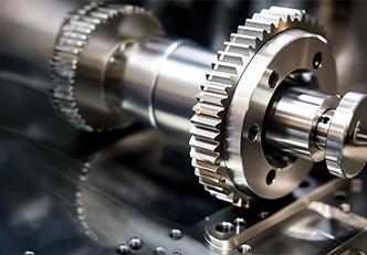
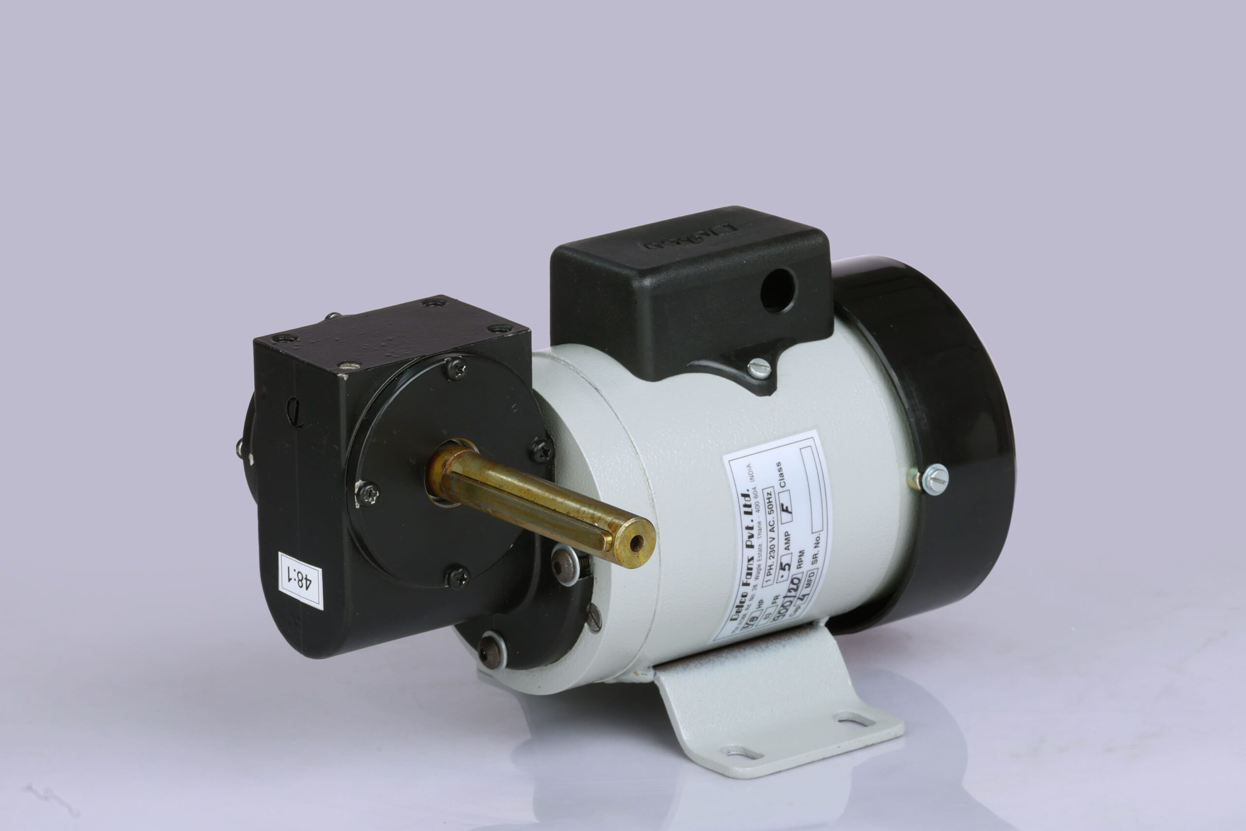
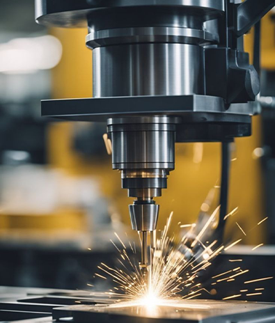
Delco right angle worm geared electric motor detail view Precision machining of electric motor gear shafts at Thane plant Delco Fans since 1974 emblem
Engineering Mechanics & Information Gain

Kinematics and Thermal Dynamics of Industrial Worm Geared Electric Motors

Worm geared electric motors represent the cornerstone of compact, right-angle mechanical power transmission. By meshing a hardened steel worm screw with a high-tensile phosphor bronze worm wheel, these drive units deliver massive torque multiplication within a footprint significantly smaller than equivalent inline helical systems.

For global procurement managers and mechanical design engineers, evaluating a worm gearhead goes far beyond basic motor wattage. Understanding the physical realities of sliding friction, tooth lead angles, thermal dissipation thresholds, and structural deflection under radial loads is critical to achieving long service life in demanding industrial environments.

Key Kinematic Principles of Delco Worm Drives

  • Sliding Contact Thermodynamics: Unlike spur or helical gearing which transfers energy through rolling contact, worm gearing relies on sliding engagement along the tooth flanks. Delco utilizes case-hardened alloy steel (20CrMnTi / 8620) ground to fine tolerances mated with centrifugally cast CuSn12 phosphor bronze wheels to maintain low friction coefficients under sustained loads.
  • Static vs. Dynamic Self-Locking: Gear ratios exceeding 30:1 with worm lead angles ($\gamma$) below 4° to 5° inherently resist back-driving from the output side. This self-locking property provides inherent holding capability for inclined conveyors, overhead hoists, and positioning stages—though safety-critical systems should always incorporate secondary electromechanical brakes.
  • Thermal Rating Power Limits ($P_{th}$): Because sliding friction generates heat, the continuous output rating of a worm gearmotor is often governed by thermal dissipation rather than mechanical tooth strength. Delco housings are engineered with high-surface-area aluminum alloy or ribbed cast iron cooling fins to keep oil sump temperatures safely below 85°C.
  • Backlash Control & Torsional Rigidity: Standard industrial backlash ranges from 15 to 30 arcminutes, perfectly balanced for general conveyor and indexing duty. For high-precision automated systems, Delco offers precision-hobbed low-backlash sets tailored to minimize mechanical hysteresis.
Send an Inquiry
Product Portfolio

Featured Worm Geared Electric Motor Configurations

Engineered to integrate seamlessly with single-phase AC, three-phase industrial mains, and DC/BLDC power sources. Explore our primary OEM series below.

Send an Inquiry
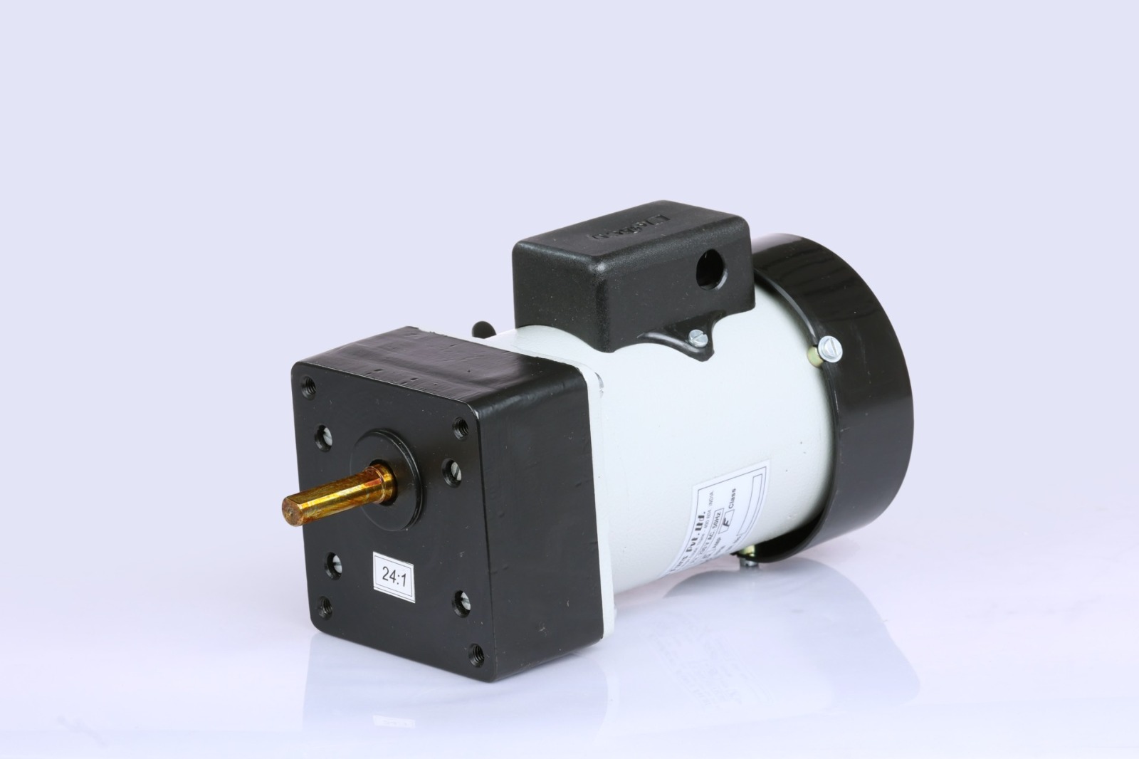
Standard Right Angle Worm Geared Electric Motor

WGM Series: Heavy Duty Right-Angle Motor

Industrial three-phase worm gearmotors designed for continuous S1 operation on conveyors, agitators, and heavy packaging lines.

  • Power: 0.12 kW – 7.5 kW
  • Gear Ratios: 7.5:1 to 100:1
  • Torque Output: 15 Nm up to 500 Nm
  • Housing: Die-cast Aluminum / Cast Iron
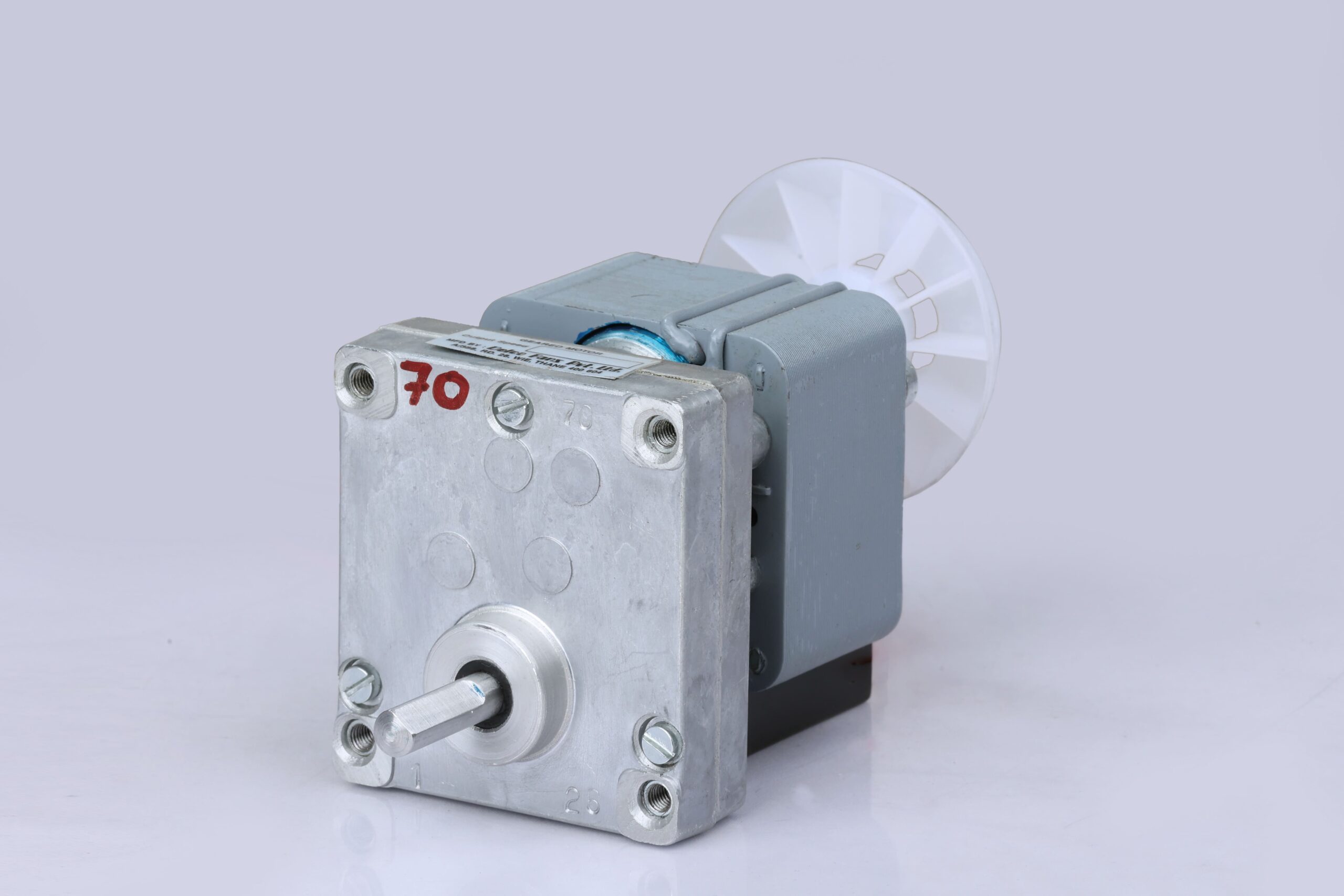
Compact Shaded Pole Worm Geared Motor

Fractional & Shaded-Pole Worm Motors

Ultra-compact single-phase fractional horsepower worm drives tailored for commercial appliances, vending mechanisms, and HVAC damper control.

  • Power: 5W – 180W FHP
  • Output Speed: 1 RPM – 120 RPM
  • Thermal Protection: Impedance / Automatic Reset
  • Mounting: Multi-position Foot/Flange
Hollow Shaft Worm Gearmotor Assembly

WGM-H Series: Hollow Bore Right-Angle Drives

Direct shaft-mounted worm gearmotors featuring internal keyways or shrink discs, eliminating flexible couplings and alignment hassle.

  • Bore Diameter: 14mm – 42mm keyway
  • Mounting: Torque Arm / Reaction Bar
  • Ingress Protection: IP55 / IP66 Dual Lip Seals
  • Efficiency: Optimized tooth profile
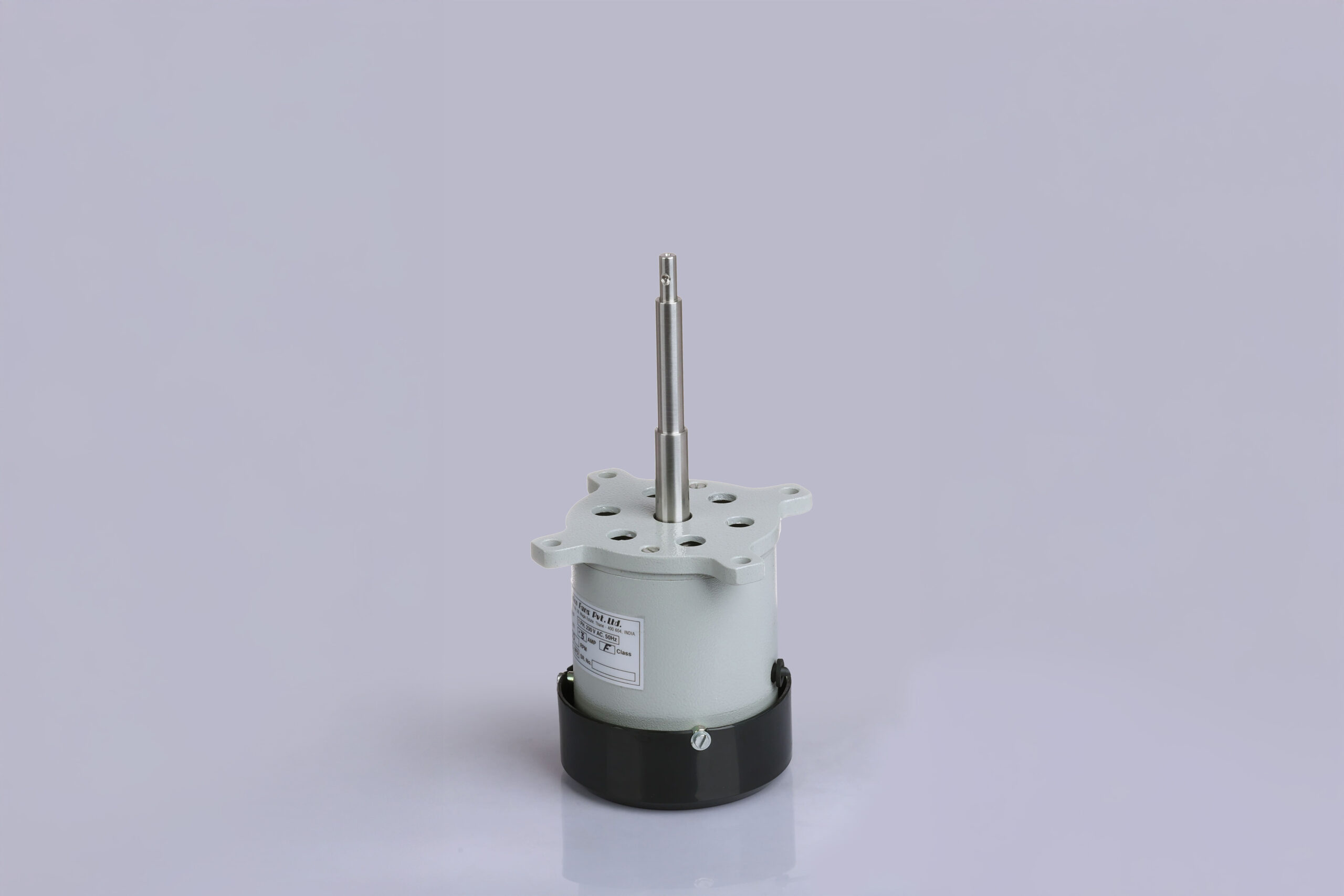
Special Purpose Custom Worm Geared Motor

Custom Purpose OEM Geared Motors

Purpose-built right-angle drives featuring custom shaft turnings, non-standard voltages, extreme temperature grease, and specialized coatings.

  • Customization: Shaft, Winding, Flange
  • Duty Cycles: Continuous S1 / Intermittent S3
  • Certifications: CE / ISO Compliance
  • Testing: 100% Load & Sound Bench Verified
Technical Comparison Matrix

Engineering Selection: Worm vs. Helical vs. Planetary Gearheads

Selecting the ideal drive technology requires balancing spatial envelope, thermal efficiency, mechanical cost per Newton-meter, and operational noise.

Detailed comparison between Worm Geared Motors, Inline Helical Motors, and Planetary Gearboxes for B2B buyers
Selection Parameter Worm Geared Electric Motor Inline Helical Geared Motor Planetary Gearbox Drive
Output Axis Orientation Right-Angle (90° Offset) Inline / Parallel Co-axial Inline / Co-axial Alignment
Reduction Ratio per Stage High (5:1 up to 100:1 single stage) Moderate (3:1 to 10:1 per stage) Moderate (3:1 to 10:1 per stage)
Mechanical Efficiency (at 40:1) 65% – 82% (sliding friction dependent) 92% – 96% (rolling gear mesh) 90% – 95% (multi-planet mesh)
Backlash Range 15 to 30 arcmin (Standard) 10 to 20 arcmin 1 to 7 arcmin (Precision)
Self-Locking Capability Yes (Static self-locking at ratios > 30:1) No (Easily back-driven) No (Easily back-driven)
Acoustic Noise Level Ultra-Quiet (< 58 dBA sliding engagement) Moderate (62 – 72 dBA) Higher pitched (68 – 78 dBA)
Shock Load & Vibration Resistance High (Dampened by continuous gear contact surface) Moderate High (Power split across planet gears)
Relative Acquisition Cost ($/Nm) Lowest / Most Economical for Right-Angle Moderate Highest Premium
E-E-A-T Enterprise Credibility

50+ Years of Manufacturing Integrity: Why OEMs Rely on Delco Fans

Founded in 1974 in Wagle Industrial Estate, Thane, Maharashtra, Delco Fans Pvt. Ltd. has built an unshakeable reputation for shop-floor engineering excellence and uncompromising quality control.

We do not operate merely as a catalog distributor or simple gear assembler. Every worm geared electric motor that leaves our facility is built from raw raw materials through rigorous in-house manufacturing steps:

  • In-House Gear Hobbing & Shaft Grinding: CNC gear hobbers produce precise tooth geometries with controlled lead angles, ensuring maximum contact pattern overlay and minimum vibration.
  • Precision Stator Winding & VPI Treatment: Pure electrolytic copper coils are wound in-house and subjected to Vacuum Pressure Impregnation (VPI) with Class F/H insulation varnishes to withstand harsh thermal cycling.
  • Dynamic Rotor Balancing: Every rotor assembly undergoes high-speed dynamic balancing to ISO 1940 standards, preventing radial bearing load fatigue and seal degradation.
  • Documented Batch Load Testing: Finished geared motors are bench-tested for no-load current draw, full-load thermal rise, acoustic noise levels, locked-rotor torque, and gear backlash before dispatch.
  • Custom Engineering Adaptability: From modified shaft steps, keyways, and splines to custom mounting brackets and dual-voltage windings, our engineering desk collaborates directly with OEM design teams.
Send an Inquiry
Delco engineering team evaluating motor assembly precision Precision motor component manufacturing at Delco Thane plant
Technical FAQ & Search Intent Answers

Frequently Asked Questions by Global OEM Purchasing Teams

Direct engineering insights addressing real-world queries encountered during worm geared motor selection and procurement.

Calculating the correct Service Factor ($F_s$) is critical to preventing tooth fatigue, pitting, and shaft shearing under real-world operating conditions. The service factor formula modifies your required output torque ($T_{req}$) based on three operational variables:

$$T_{rated} \ge T_{req} \times F_s$$

Where $F_s = F_{load} \times F_{duty} \times F_{freq}$:

  • Load Characteristic ($F_{load}$): Uniform load (smooth conveyors, blowers) = 1.0; Moderate shock load (mixers, light elevators) = 1.25; Heavy shock load (crushers, heavy indexing tables) = 1.5 to 1.75.
  • Daily Operating Hours ($F_{duty}$): Under 8 hours/day = 0.9; 8–16 hours/day = 1.0; 24 hours/day continuous duty = 1.25.
  • Start/Stop Frequency ($F_{freq}$): Less than 10 starts/hr = 1.0; 10 to 100 starts/hr = 1.15; Over 100 starts/hr = 1.3+.

Our engineering team in Thane verifies these calculations against measured torque curves to ensure your selected gearhead operates within safe thermal and mechanical boundaries.

A worm gear drive exhibits static self-locking when the lead angle ($\gamma$) of the worm thread is smaller than the friction angle of the sliding tooth mesh (typically when $\gamma < 3^\circ$ to $5^\circ$, corresponding to reduction ratios of 30:1 or higher). Under static conditions, load applied to the output shaft cannot rotate the worm input shaft.

However, dynamic self-locking cannot be unconditionally guaranteed if the machinery experiences external mechanical shock, operational vibration, or oil temperature spikes that reduce the lubricant friction coefficient. In safety-critical applications—such as personnel hoists, inclined bucket elevators, or overhead doors—a worm geared motor should always be equipped with an external electromagnetic disc brake to comply with international safety regulations.

The reduction in mechanical efficiency at high ratios (e.g., 60:1 to 100:1 yielding 55%–70% efficiency vs. 7.5:1 yielding up to 88%) occurs because the worm thread lead angle narrows, increasing the relative sliding distance between the steel worm and bronze wheel for every revolution of torque delivered.

To manage heat generated by sliding friction:

  • Specify synthetic Polyalkylene Glycol (PAG) oil, which reduces the coefficient of sliding friction compared to standard mineral oils.
  • Ensure adequate free airflow around the aluminum/cast iron cooling fins on the gearbox housing.
  • Verify that the continuous absorbed power does not exceed the gearbox's rated thermal power limit ($P_{th}$). If thermal limits are exceeded, consider adding an auxiliary cooling fan or stepping down to a double-reduction helical-worm combination.

Selecting between a solid output shaft and a hollow bore shaft depends on mechanical space constraints and mounting preferences:

  • Hollow Bore Output (WGM-H Series): Mounts directly onto the driven machine's stub shaft and is secured via keyway or shrink disc. Eliminates flexible shaft couplings, alignment pillow blocks, and mounting baseplates, significantly reducing overall machine width and assembly labor. A reaction torque arm absorbs reaction forces.
  • Solid Output Shaft: Ideal for sprocket, pulley, or pinion chain drives where the gearmotor is mounted on a fixed machine pedestal. Available in single-extended or double-extended shaft profiles.

Yes. OEM customization is Delco's core strength. Because we maintain complete control over tooling, winding, machining, and assembly at our Thane facility, we routinely supply custom OEM builds including:

  • Non-standard shaft extension diameters, keyways, flat steps, and splines.
  • Custom input voltage/frequency combinations (e.g., 110V 60Hz, 220V 50Hz, 380V/415V/460V 50/60Hz, and low-voltage DC).
  • IP65/IP66 washdown protection with stainless steel shafts and viton dual-lip oil seals for food processing or outdoor duty.
  • Custom stator insulation classes (Class H up to 180°C) and custom paint/coating finishes.

Small-to-medium frame aluminum gearboxes (Sizes 030 through 090) are factory-filled with premium synthetic PAG grease/oil and are sealed for life under standard operating ambient temperatures (-20°C to +40°C), requiring zero oil changes during their service life.

For heavy-duty cast iron housings (Sizes 110 and above) filled with mineral gear oils, an initial oil flush and change is recommended after the first 500 operating hours, followed by routine fluid changes every 4,000 to 8,000 operational hours (or at least once every two years), whichever comes first.

Application Spectrum

Proven Performance Across Critical Industrial Sectors

Delco Worm Geared Electric Motors operate inside machinery where non-stop reliability, high reduction, and space efficiency are mandatory.

Conveyor and Material Handling Icon

Conveying & Material Handling

Belt conveyors, roller indexing tables, sorting systems, and automated warehouse transfer lines.

Inquire Now
Packaging Equipment Icon

Packaging & Bottling Lines

Capping machines, rotary labeling tables, carton erectors, and shrink-wrapping machinery drives.

Inquire Now
Valve Actuation and Gate Control Icon

Valves, Dampers & Actuators

High-ratio self-locking right-angle drives for dam gates, sluice valves, and HVAC damper positioners.

Inquire Now
Food Processing Equipment Icon

Food & Commercial Equipment

Commercial dough mixers, rotisserie drives, vending dispensers, and laboratory positioning tables.

Inquire Now

Start Your Worm Geared Motor OEM Inquiry Today

Contact our engineering desk in Thane to discuss gear ratio selection, torque curves, custom shaft profiles, or batch pricing for your manufacturing schedule.

Send an Inquiry Contact Us Directly