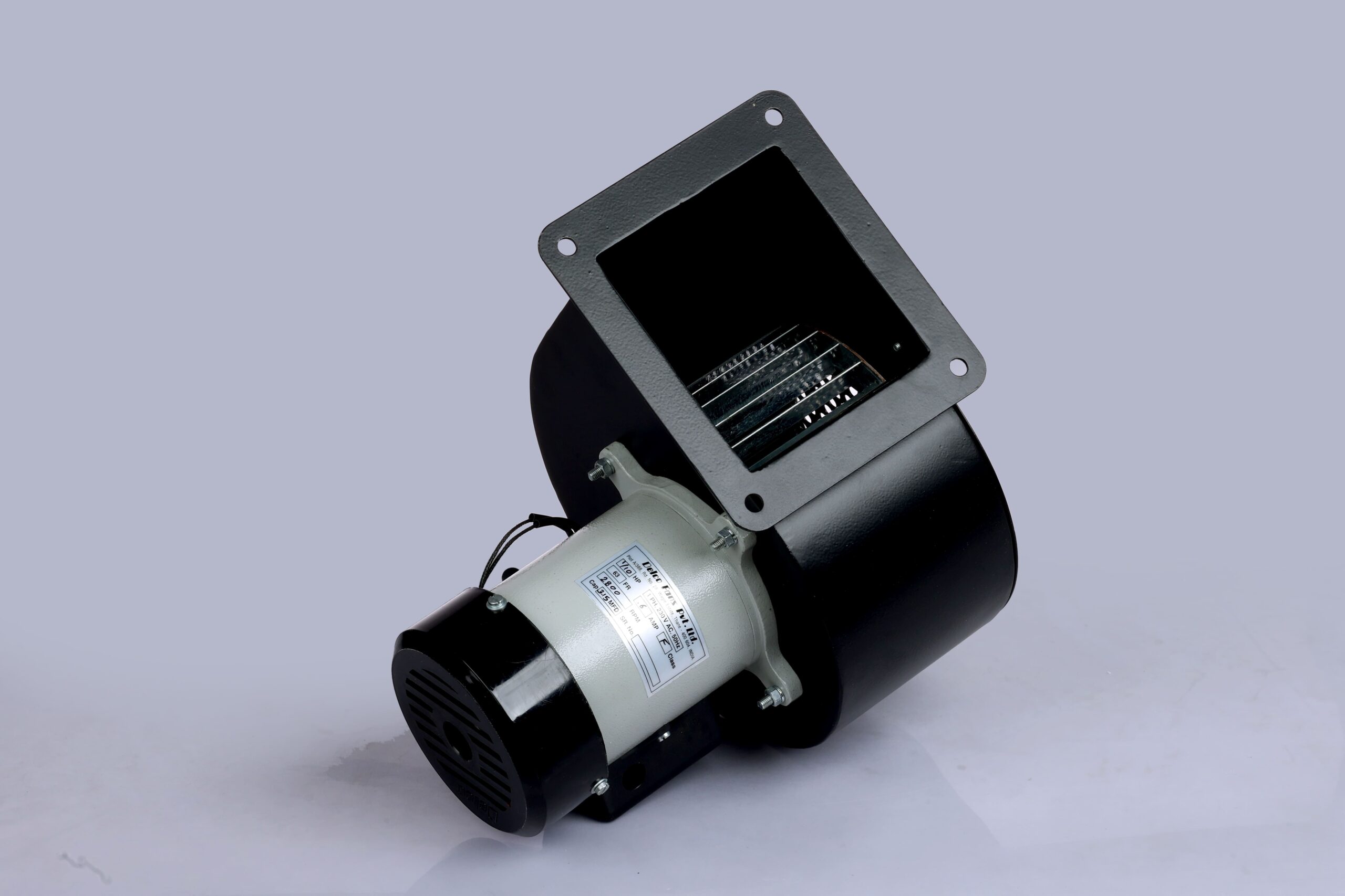
Standard Heavy Duty Centrifugal Blowers
Engineered for high static pressure ducted ventilation, burner air injection, and panel cooling. Features durable sheet metal scroll housings and direct-drive AC motors.


Comprehensive technical handbook for design engineers and global buyers. Sizing duty points, aerodynamic scroll dynamics, AC vs. EC performance curves, and future air movement trends.
When global OEM procurement teams and HVAC system integrators evaluate air movement technologies, Centrifugal Blowers stand out as the definitive solution for high-resistance, ducted, and filtered thermal management applications. Unlike axial flow fans—which propel air parallel to the impeller shaft at high volumes but low static pressures—a centrifugal blower draws air axially into the center of a rotating impeller wheel and accelerates it radially outward at a 90-degree angle into a volute scroll housing.
This kinetic conversion process converts angular rotational momentum into static and velocity pressure. The volute housing gradually expands in cross-sectional area, allowing the high-velocity air exiting the impeller blades to decelerate smoothly, converting dynamic kinetic energy into usable static pressure (Ps). This fundamental fluid-dynamic principle enables centrifugal blowers to force air through dense HEPA filters, intricate heat exchangers, multi-bend ductwork, and tightly packed industrial electronic cabinets where axial fans stall or experience total flow breakdown.
For technical procurement managers evaluating speed control, temperature rise, and power consumption, the performance of any centrifugal blower responds directly to the fundamental Fan Affinity Laws:
Understanding these laws allows design engineers to optimize duty points by adjusting motor speed via 0-10V EC signals or frequency drives, preventing system over-sizing and reducing operational thermal stress.
Delco Fans Pvt. Ltd. designs and manufactures a comprehensive portfolio of single inlet, double inlet, backward curved, and custom EC centrifugal blowers tailored to demanding global duty cycles.
Engineered for high static pressure ducted ventilation, burner air injection, and panel cooling. Features durable sheet metal scroll housings and direct-drive AC motors.
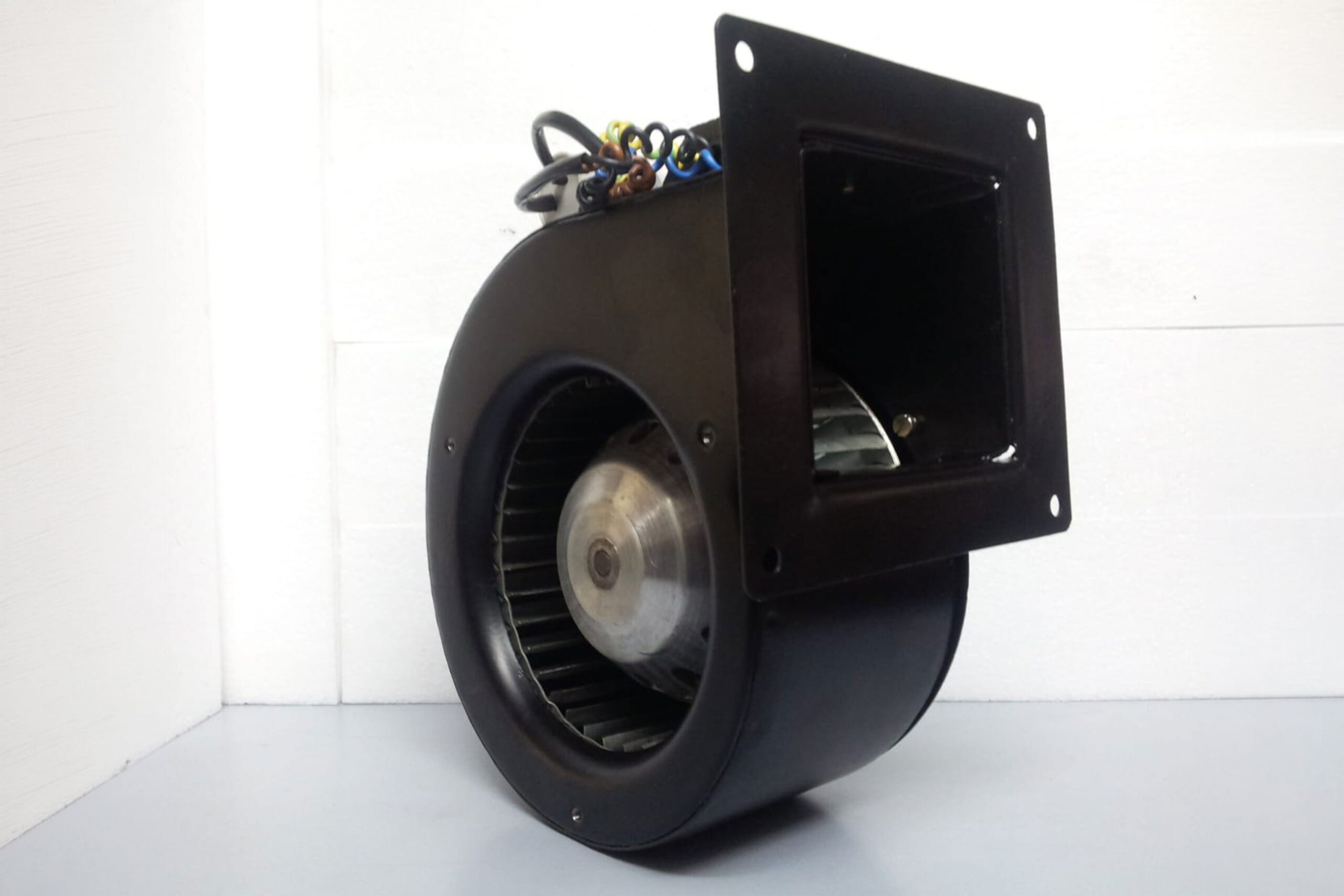
Ultra-compact axial profile utilizing external rotor technology. Ideal for space-constrained medical equipment, laboratory analyzers, and surgical clean benches.
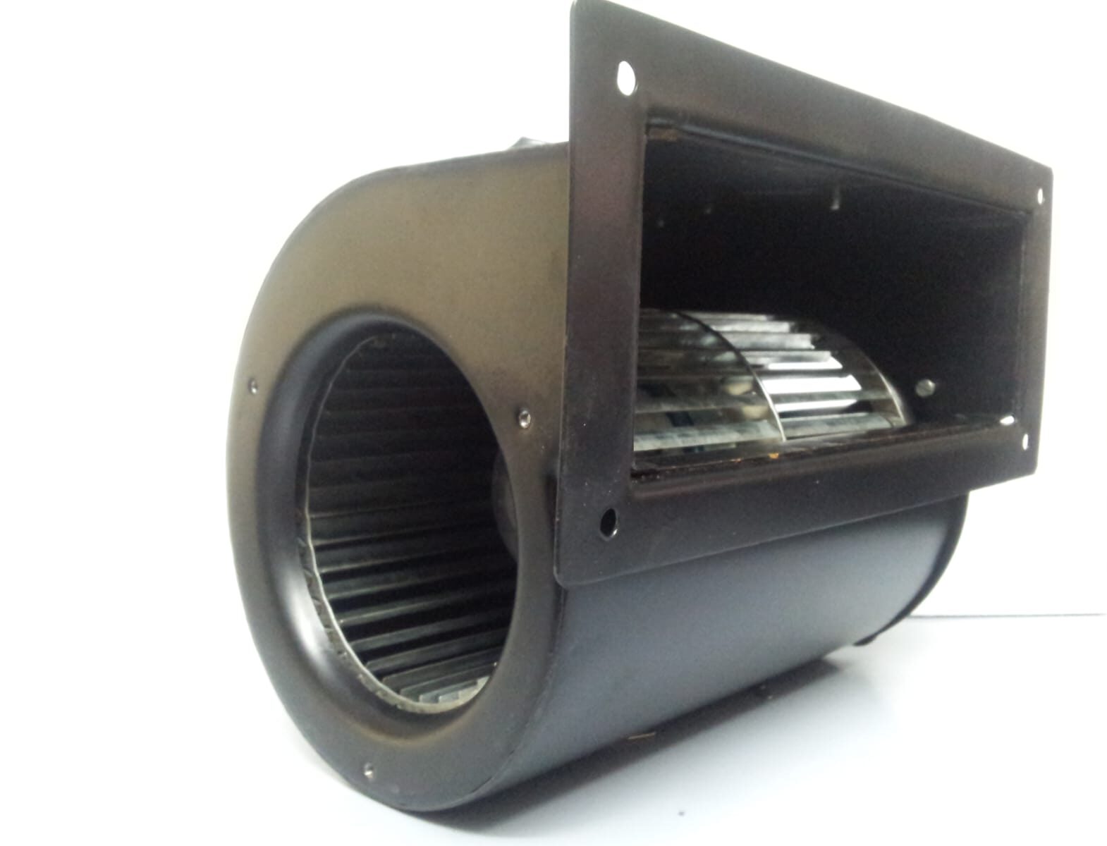
Twin suction inlets provide double the volumetric airflow within a compact width footprint. Essential for HVAC fan coils, air curtains, and evaporative cooling units.
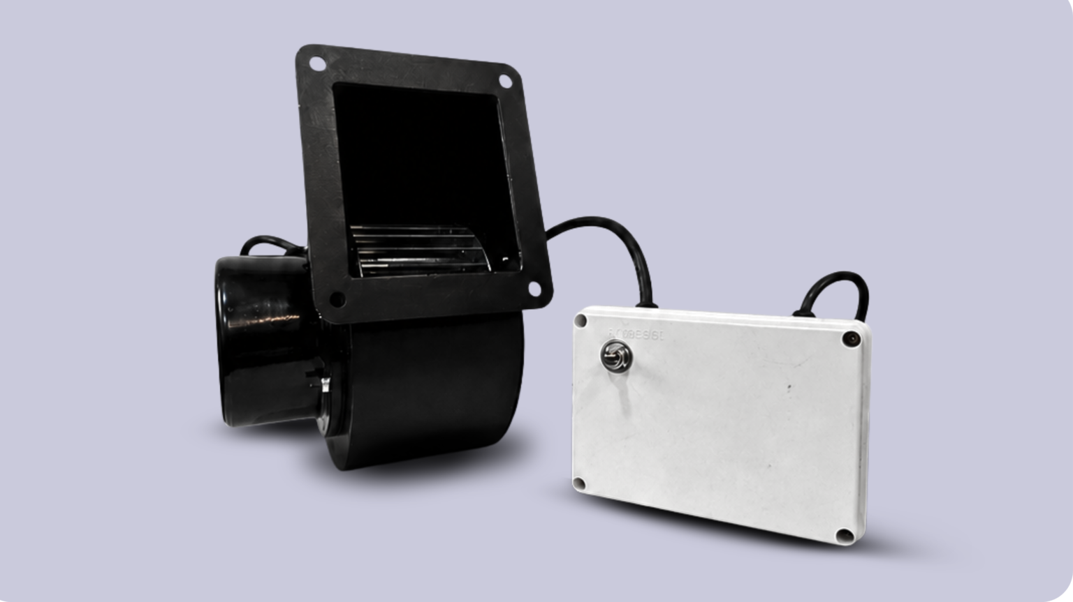
Electronically Commutated (EC) motorized blowers featuring 0-10V/PWM closed-loop speed feedback, lowering energy consumption by up to 50% under partial load conditions.
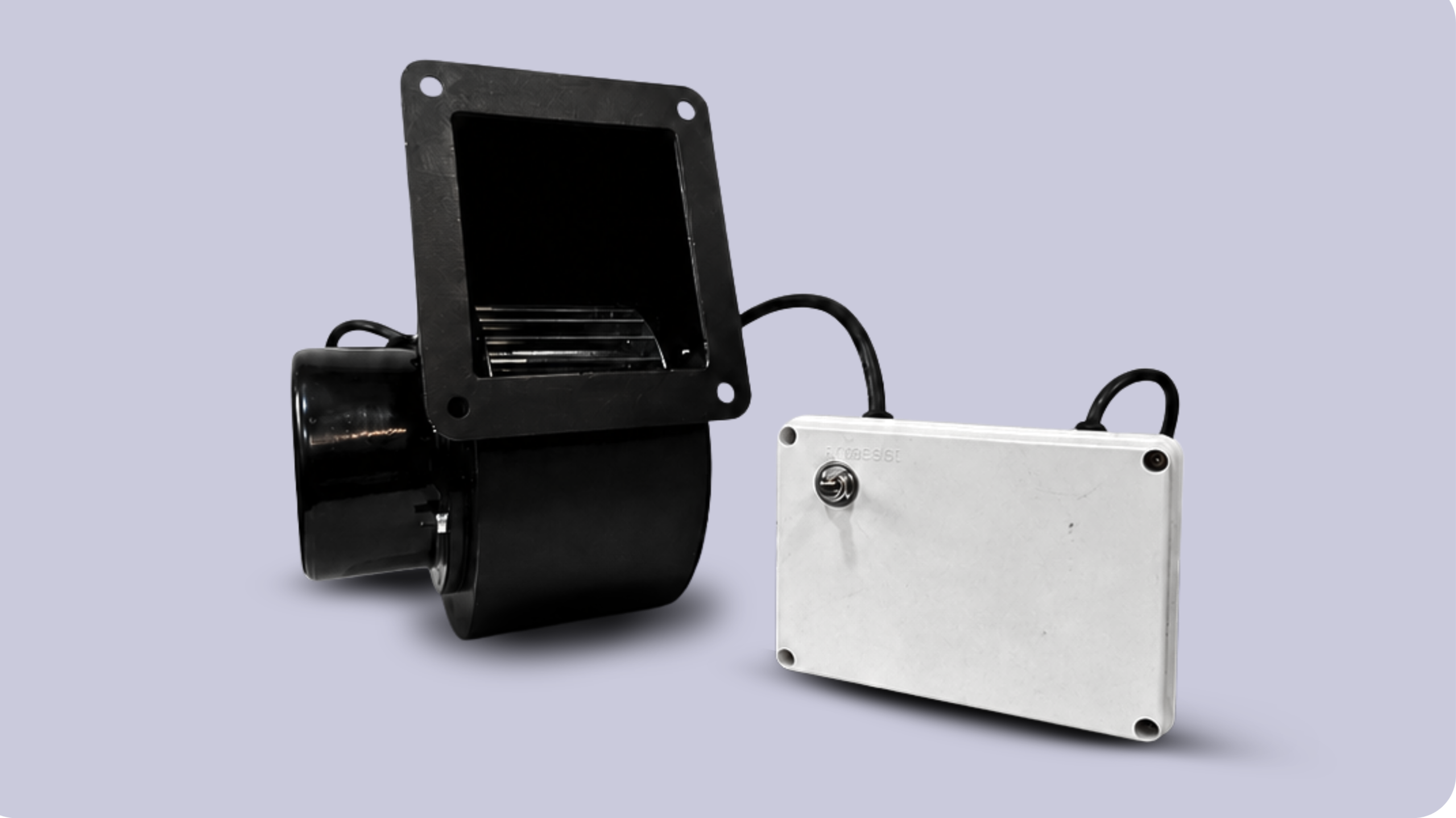
Non-overloading high-efficiency impellers designed for unhoused plenum applications, air purification units, and modern heat recovery ventilators.
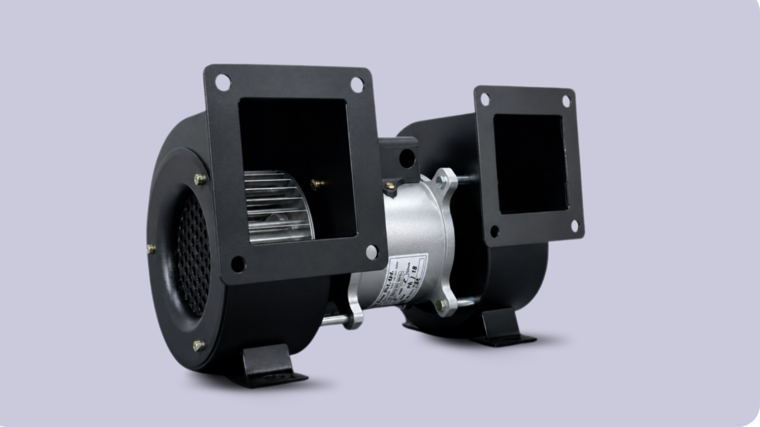
Dual-sided fractional horsepower blowers custom-configured with specialized mounting brackets, dual outlets, and custom harness terminations for serial OEM machinery.
Compare performance parameters across Delco’s standardized and OEM custom centrifugal blower series to identify the correct physical and thermodynamic envelope.
| Blower Architecture | Impeller Diameter Range | Max Airflow Capacity | Static Pressure Range | Motor Technology | Primary OEM Applications |
|---|---|---|---|---|---|
| Single Inlet (Standard Scroll) | 120 mm – 315 mm | 250 to 2,200 CFM | 150 Pa – 1,200 Pa | AC Shaded Pole / FHP Induction | Packaging machinery, electrical panels, industrial ovens |
| Single Inlet (External Rotor) | 133 mm – 250 mm | 180 to 1,450 CFM | 200 Pa – 850 Pa | AC / EC External Rotor | Medical sterilizers, fume hoods, telecom enclosures |
| Double Inlet (Ducted) | 140 mm – 280 mm | 450 to 3,800 CFM | 100 Pa – 650 Pa | AC FHP Direct Drive | HVAC fan coils, air curtains, commercial refrigeration |
| Backward Curved Impeller | 175 mm – 400 mm | 300 to 4,500 CFM | 250 Pa – 1,500 Pa | EC Brushless DC / AC Induction | Cleanrooms, HEPA filtration, server rack cooling |
| Customized EC High-Static | 120 mm – 355 mm | 200 to 5,000 CFM | up to 2,000 Pa | EC Smart Speed Controllable | Variable load air purifiers, precision lab equipment |
Selecting the optimal centrifugal blower for an OEM application requires a thorough understanding of blade aerodynamic geometry. The angle and curvature of the impeller blades fundamentally determine the performance curve, noise profile, operating efficiency, and total cost of ownership (TCO).
Forward-curved impellers feature a large quantity (typically 30 to 60) of small blades curved forward in the direction of rotation. They generate high static pressures at relatively low rotational speeds (RPM), enabling compact housing footprints and quiet operation.
Procurement Insight: Forward-curved blowers are extremely sensitive to system pressure drops. Operating a forward-curved blower in zero-resistance conditions (free delivery) can cause motor overload due to its steep power-demand curve. Always ensure the system resistance matches the operating point.
Backward-curved impellers consist of fewer, larger blades (typically 8 to 14) curved away from the direction of wheel rotation. Air exits the wheel at lower velocities, yielding fluidic efficiencies exceeding 75% to 85%.
Procurement Insight: Backward-curved impellers possess a self-limiting power characteristic. Power consumption reaches a peak within the normal operating range, preventing motor burnout even if static pressure drops unexpectedly. Perfect for variable-filter systems.
To avoid specifying an over-sized blower that wastes energy, or an under-sized unit that fails to cool electrical components or maintain cleanroom air exchanges, engineers must follow a four-step calculation process:
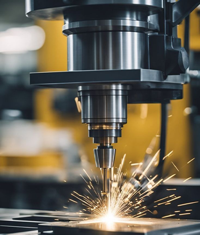
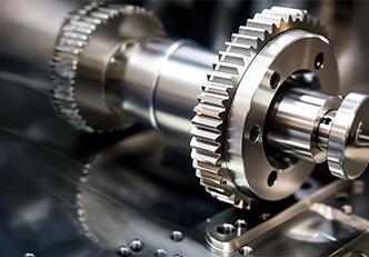
Established in 1974 in Wagle Industrial Estate, Thane, India, Delco Fans has accumulated over five decades of continuous manufacturing excellence in fractional horsepower motors, geared drives, and centrifugal blowers.
Unlike asset-light trading companies or catalogue distributors, Delco manages the entire production lifecycle in-house—from stator lamination pressing, copper wire precision winding, and rotor dynamic balancing to volute housing fabrication, powder coating, and 100% routine electrical/dielectric safety testing.
As industrial automation, medical electronics, server infrastructure, and commercial HVAC equipment evolve, global procurement parameters for centrifugal blowers are shifting rapidly. Buying decisions are no longer made solely on initial purchase price; they are governed by total lifecycle costs, energy efficiency regulations, smart connectivity, and supply chain resilience.
The global transition from traditional AC induction motors to Electronically Commutated (EC) permanent magnet motors is accelerating. EC blowers combine AC mains power input with DC brushless internal motor architecture, eliminating rotor copper losses and achieving IE4/IE5 efficiency levels. Integrated microelectronics enable continuous closed-loop speed control via 0-10V, PWM, or Modbus RTU communication networks, allowing air systems to dynamically adjust speed based on real-time filter clogging or thermal load changes.
In medical diagnostic equipment, residential heat recovery systems, and cleanroom installations, low noise output is a critical design requirement. Future centrifugal blowers feature aero-acoustically optimized scroll diffusers, skewed impeller blade passages, and bio-inspired inlet rings that minimize turbulence vortices, reducing operating sound levels by up to 4 to 6 dBA.
Modern industrial blowers are increasingly equipped with embedded vibration, temperature, and current sensors. Connected via Modbus or fieldbus interfaces, these smart blowers feed operational telemetry into central PLCs or cloud platforms, alerting maintenance engineers to bearing wear or impeller unbalance long before catastrophic thermal shutdown occurs.
Global original equipment manufacturers are actively diversifying their supply chains away from single-country dependence. India’s mature engineering ecosystem, supported by established manufacturers like Delco Fans Pvt. Ltd., offers world-class quality standards, competitive manufacturing economics, robust IP protection, and highly adaptable OEM engineering capabilities.

“Integrating Delco’s custom single inlet centrifugal blowers into our medical diagnostic equipment line resolved our severe enclosure static pressure constraints. Their technical team modified the scroll flange dimensions and terminal harness to fit our chassis perfectly. Zero field failures over three years of continuous serial delivery.”

“Delco’s backward-curved EC centrifugal blowers gave us a major edge in energy performance for our HVAC air purification units. Their in-house dynamic balancing ensures exceptionally quiet operation, which is critical for hospital installations. Extremely reliable supplier out of Thane, India.”

Clear, authoritative technical answers addressing common search intent and procurement queries submitted to AI tools by thermal design engineers.
Collaborate directly with Delco’s senior airflow design engineers in Thane, India. We tailor scroll housings, impellers, and motor windings to your precise OEM duty point.