
+91 98209 33660
Explore our foundational gearhead motor series engineered for custom reduction ratios, heavy radial loads, and severe-duty OEM applications.
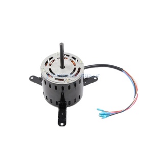
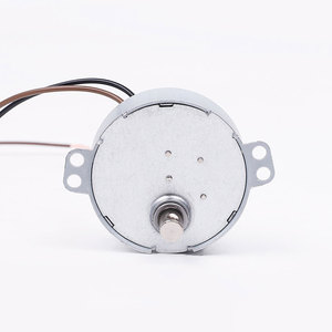
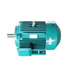
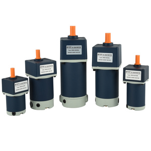
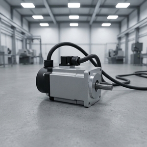
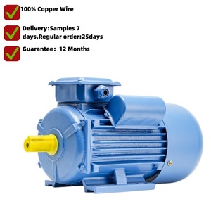
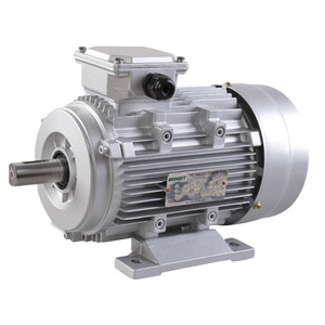
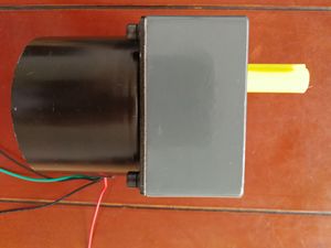
In modern industrial automation, power transmission efficiency is dictated by the thermal limits, mechanical backlash, and gear tooth meshing accuracy of speed reducers. Selecting off-the-shelf speed gearboxes frequently results in operational compromises—ranging from premature micro-pitting under shock loads to severe thermal power dissipation failures.
As a specialized Custom OEM Speed Reducer Manufacturer & Factory, our engineering philosophy revolves around duty-cycle optimization. By tailoring gear tooth geometry, metallurgical heat treatments, and housing rigidity to exact machine envelopes, we eliminate over-sizing while guaranteeing continuous 24/7 service life.
Founded on over five decades of direct shop-floor manufacturing expertise (established in 1974), our facilities integrate in-house precision gear hobbing, CNC machining, automated stator winding, and dynamic load testing. This end-to-end sovereignty ensures absolute batch-to-batch consistency for global equipment OEMs.
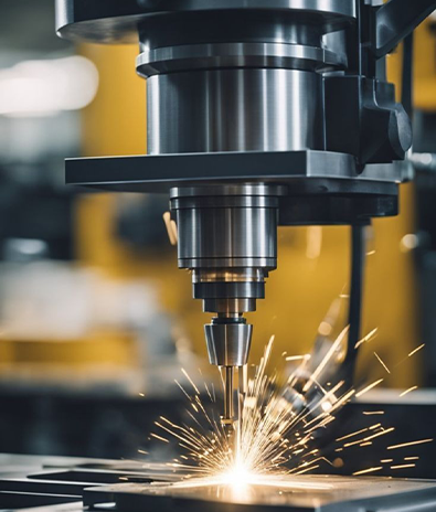
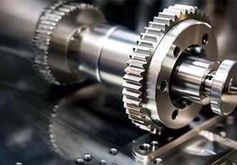
Selecting the optimal reduction mechanism requires evaluating ratio requirements, input speeds, radial shaft overhang, and target mechanical efficiency.
| Gearhead Topology | Typical Reduction Ratios | Mechanical Efficiency | Backlash Range | Key OEM Application Suits |
|---|---|---|---|---|
| Inline Helical Speed Reducer | 3:1 – 280:1 (Multi-stage) | 95% – 98% per stage | 10 – 20 Arcmin | Heavy material handling, continuous conveyors, fluid pumps |
| Right-Angle Worm Speed Reducer | 7.5:1 – 100:1 | 55% – 90% (Lead angle dependent) | 15 – 35 Arcmin | Compact automation drives, self-locking hoists, packaging lines |
| Precision Planetary Speed Reducer | 3:1 – 100:1 | 92% – 97% | < 3 – 8 Arcmin | Servo positioning, robotics, CNC rotary tables, automated guided vehicles |
| Shaded Pole & FHP Geared Motors | 10:1 – 1500:1 | 60% – 82% | 20 – 45 Arcmin | Medical instruments, HVAC dampers, vending machines, valve actuators |
*Note: All speed reducer units manufactured in our factory can be fully modified with custom NEMA/IEC motor input flanges, solid/hollow output shaft keyways, and synthetic lubricant grades for low-temperature operating environments (-40°C to +80°C).
From initial tooth contact analysis to high-volume series manufacturing, our facility is optimized to meet stringent mechanical specifications.
We utilize premium 20CrMnTi alloy steels for worm shafts and helical gears, undergoing vacuum carburizing and oil quenching to achieve surface hardness of HRC 58-62 while maintaining a ductile core to absorb sudden shock loads.
By controlling gear hobbing, tooth grinding, and housing machining on CNC centers within our own factory, we eliminate third-party lead times and ensure strict concentricity tolerances across output shafts and motor mounts.
High acoustic noise in gear reducers is caused by profile distortion during heat treatment. Our gear modification techniques (crown honing and root relief) reduce contact stress spikes and produce smooth, quiet meshing (< 50 dBA).
To prevent lubricant leakage and ingress of particulate contaminants in outdoor or washdown applications, every reducer is fitted with high-fluororubber (Viton) dual-lip oil seals and leak-tested under pneumatic pressure.
Whether your assembly requires custom terminal box orientations, specialized thermal cutouts (Class H 180°C insulation), IP65/IP67 ingress ratings, or unique shaft flats, our engineering team adapts to your exact STEP drawings.
Prior to dispatch, 100% of manufactured speed reducers undergo no-load current checks, output torque verification, thermal rise benchmarking, and dynamic backlash measurement on automated test beds.
Global equipment builders are shifting purchasing criteria from initial unit cost toward total cost of ownership (TCO), modularity, and integration readiness.
Machine builders are demanding higher continuous output torque ($T_2$) from smaller frame sizes ($L$). Advancements in tooth geometry optimization, high-load needle roller bearings, and synthetic lubricants allow custom OEM speed reducers to operate at elevated thermal power limits without expanding the machine footprint.
Future speed reducer procurement specs increasingly require factory-integrated vibration sensors, oil-level sight ports, and thermal RTD probes. Sensor-enabled gearboxes communicate directly with Industry 4.0 PLCs, alerting maintenance managers to micro-pitting or seal wear before catastrophic mechanical breakdown occurs.
Energy regulations across Europe, North America, and Asia-Pacific are driving a transition toward IE3/IE4 asynchronous motors and brushless EC/PM motors. OEM speed reducers must maintain high mechanical efficiency (>96% per stage) so that systemic efficiency gains are not squandered by gear friction losses.
Reliance on standard catalog distributors introduces delivery risk and rigid lead times. Global buyers are forming direct strategic partnerships with agile gearhead manufacturers that provide custom shaft lengths, specialized mounting flanges, and guaranteed volume buffer stock for seamless production line replenishment.
To avoid premature gear teeth degradation or thermal overload, application engineers must calculate key load metrics prior to ordering standard or custom units.
Clear engineering answers regarding customized speed reducer manufacturing, lead times, and quality standards.
We provide comprehensive customization including exact reduction ratios (from 3:1 to 1500:1), custom output shaft profiles (keyed, splined, hollow bore, D-shaft), specialized mounting flanges (NEMA, IEC, custom step patterns), low-backlash gear grinding, IP65/IP67 seals, high/low ambient temperature synthetic lubricants, and custom paint/coating finishes.
All critical components—housing casings, shafts, worm wheels, and spur gear teeth—are processed on automated CNC hobbing machines and machining centers. Dimensions are verified using 3D Coordinate Measuring Machines (CMM) and optical gear mesh analyzers in an environment-controlled QA lab.
For custom engineering prototypes with specialized shafting or gear ratios, typical sample delivery is 2 to 3 weeks. Once prototype approval is secured, series OEM production runs are typically dispatched within 3 to 4 weeks, with buffer stock programs available for long-term supply agreements.
Tooth surface hardness directly dictates wear resistance and fatigue limit. We employ computer-controlled carburizing and nitriding processes that achieve high surface hardness (HRC 58-62) to resist micro-pitting while maintaining a tough core structure to prevent tooth breakage during sudden mechanical overloads.
Yes. Our modular input flange system allows seamless coupling with AC induction motors, Brushless DC (BLDC) motors, permanent magnet synchronous motors (PMSM), stepper motors, and standard NEMA/IEC servo motors.
Every single reducer unit undergoes 100% factory inspection prior to packaging. This includes no-load operational checks to verify current draw and rotational smoothness, acoustic noise measurement (NVH), pressure leak testing on shaft seals, and static backlash verification.
Send us your speed, torque, mechanical envelope drawings, or target duty cycle. Our senior mechanical application engineers will provide complete technical proposals, 3D STEP models, and competitive OEM factory quotes.